In the previous post, I described how an audio signal is represented. Now, let’s discuss the various physical forms that audio signals take as they travel through each stage of an audio playback system.
For the sake of this discussion, I am going to assume the most common and straightforward use case: playing a digital stream over loudspeakers (or headphones). By “digital stream” I mean any audio signal that is processed by a computer or computer-like system; that can be anything including a MP3 file, online video, online music streaming, the soundtrack of a Blu-ray disc, etc. This does not include analogue media such as vinyl discs or cassette tapes.
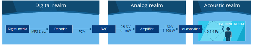
Before this digital content can reach your eardrums, it has to go through a series of steps. Between these steps, the audio signal is materialized in different ways depending on which part of the audio “pipeline” we are looking at. In this post I refer to these concrete representations as realms [note] “realm” is not a widely used term — the term “domain” is normally used. However, I felt that this could create confusion with time domain and frequency domain, which are completely unrelated concepts. [end note] . I am going to start at the source and then make my way through to the listener.
To keep things clear and simple, the example signal I’ll use throughout this post is a monophonic (one channel) 1 kHz sine wave. For all intents of purposes, each additional channel can be assumed to act like a completely separate audio signal that takes a similar path through the system.
The digital realm
It all starts within the digital device, which can be any computer or computer-like gadget (PC, smartphone, Bluetooth receiver, etc.). Most devices read or receive audio data in digitally compressed form. Popular digital compression algorithms include MP3, AAC and FLAC.
Digital compression [note] Not to be confused with dynamic range compression, which is completely unrelated. [end note] is a complicated subject, which I won’t dig into further in this post. In any case, the data first goes through a decoder which converts the compressed signal into uncompressed form, which looks like this:
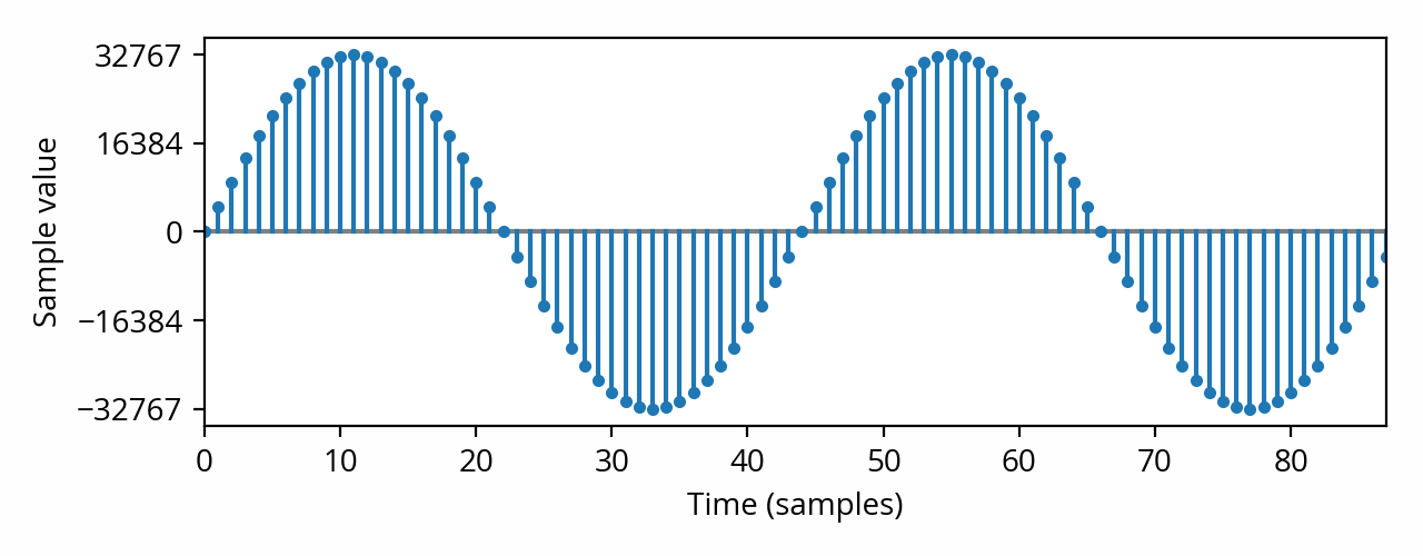
This plot shows that, in the digital realm, audio is not represented by a continuous, smoothly changing signal — instead, all we have are regularly-spaced “snapshots” that indicate what the signal amplitude is at some point in time. This is called a discrete signal, and the “snapshots” are called samples. In this example, we have 44100 samples every second, or more formally, the sample rate is 44.1 kHz. Such a sample rate is standard for music — other types of content, such as movies or games, use a slightly higher rate, 48 kHz, for mostly historical reasons.
Because memory is not infinite, each sample value has a finite precision. In practice, each sample is typically converted to a signed integer with a precision, or bit depth, of 16 bits. This process is called quantization. A 16-bit signed integer can take a value from -32768 to +32767. Samples outside of this range cannot be represented, and will be clamped to the nearest possible value; this is called digital clipping, and is best avoided as it sounds quite bad. A signal that peaks at the highest possible amplitude without clipping is called a full-range or full-scale signal [ref] IEC 61606–1:2009, Digital audio parts — Basic measurement methods of audio characteristics — General, §3.1.10 [end ref] .
Finally, the signal is physically represented simply by transmitting the value of each point, or sample, one after the other. For example, the above signal is transmitted as 4653, 9211, 13583, etc. in the form of binary numbers. This way of transmitting the signal is called pulse-code modulation.
This section just skirted the surface of how digital audio works. The details of how sampled signals behave in practice are often counter-intuitive; as a result, misrepresentation of digital audio phenomena is quite commonplace in the audiophile community, leading to confusion and misguided advice. Digital audio expert Chris Montgomery produced a series of videos that explains these complex phenomena with very clear and straightforward examples — it is a highly recommended resource if you wish to learn more about the digital realm.
The analog realm
Loudspeakers and headphones cannot receive a digital signal; it has to be converted to an analog signal first. This conversion is done in an electronic circuit appropriately named the digital-to-analog converter, or DAC. This is where computer engineering ends and electrical engineering begins. The main task of the DAC is to take each sample value and convert it to some electrical voltage on its output pins. The resulting signal looks like the following:
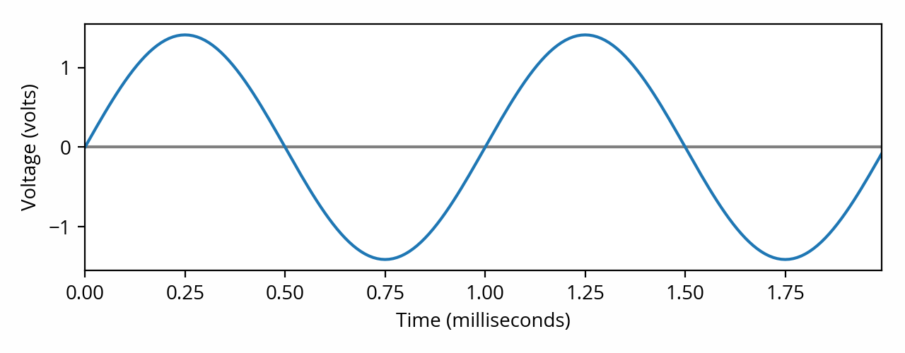
Caution: In the plot above, the unit used for the vertical scale is the volt. In other words, the amplitude of the audio signal in the analog domain is defined by its voltage. It is not defined by current nor power. Even when the signal is used as the input of a loudspeaker, it is still voltage that determines the sound that comes out; power dissipation is a consequence, not a cause, of the audio signal flowing through the loudspeaker. As Pat Brown elegantly puts it: “power is drawn, not applied”. [note] Another way to state this is to say that properly engineered analog audio devices act as voltage sources (or sinks), which are connected to each other by way of impedance bridging. [end note]
The DAC took our discrete signal and converted it into a continuous electrical signal, whose voltage is (hopefully) proportional to the digital sample value. The central (mean) value of the signal, called the DC offset, is zero volts; the signal swings around that central value, alternating between positive and negative voltage. In this example, our full-scale digital stream was converted to an analog signal that swings between -1.41 V and +1.41 V. Depending on the specific model of DAC used, its volume control setting (if any) and the signals involved, these numbers can vary — typical peak amplitude can go as low as 0.5 V [ref] Wikipedia, Nominal levels, peak amplitude for consumer audio [end ref] or as high as 2.8 V [ref] IEC 61938:2013, Guide to the recommended characteristics of analogue interfaces to achieve interoperability, §8.2.1 [end ref] .
The amount of current or power transferred from the source of an analog signal (e.g. a DAC) to the equipment plugged in at the other end of the cable (the load, e.g. a loudspeaker) is determined by the impedance of the load, also known as the input impedance. According to Ohm’s law, the lower the impedance, the more current, and therefore power, will be required to sustain a given voltage.
DACs, as well as most other types of analog audio equipment (such as filters or mixers), are not designed to provide significant amounts of power. Instead, they are meant to be connected to a high-impedance load, normally 20 kΩ or higher [ref] IEC 61938:2013, Guide to the recommended characteristics of analogue interfaces to achieve interoperability, §8.2.1 [end ref] . This means that the load is acting much like a voltmeter or oscilloscope — it is “peeking” at the input voltage without drawing significant power from it. Such a signal that carries some voltage but very little power is called a line-level signal.
On the other hand, loudspeakers (and headphones to a lesser extent) are low-impedance devices — often between 4 Ω and 8 Ω in the case of speakers. This is because they operate under a relatively low voltage, but require a lot of power. For example, most speakers will happily produce comfortably loud sound with as little as 6 V, but might consume as much as 9 watts while doing so [note] From the numbers given a keen eye will deduce that this example speaker has an impedance of 4 Ω. One thing to note is that loudspeaker impedance is highly dependent on the frequency of the signal, making the use of one number an oversimplification. The impedance that manufacturers advertise, called the rated impedance, is 1.25 times the minimum impedance of the speaker across its rated frequency range. (see IEC 60268–5:2003, Loudspeakers, §16.1) [end note] . Line-level equipment is not designed to provide such a large amount of power.
This problem is solved by using a power amplifier. This is a component that conveniently provides a high-impedance input for connecting line-level equipment, while exposing an output that is capable of providing large amounts of power, such as 10W or more, to a low-impedance load. [note] In practice, most amplifiers are also capable of increasing the voltage (amplitude) of the signal; this is called the gain of the amplifier. This is because most loudspeakers require voltages that are somewhat higher than line level in order to play loud enough. Still, the primary goal of a power amplifier is to provide power, not to increase voltage. [end note] Such outputs provide so-called speaker-level signals.
In some home audio systems, the DAC and the amplifier are integrated into one single device, which is called an integrated amplifier or more commonly an AV receiver (AVR).
The acoustic realm
Finally, in order to reach your ears, the analog signal must be converted to an acoustic signal, that is, actual sound waves. This is accomplished using a device called an electroacoustic transducer, or driver. The output of a driver when excited with our example signal, as measured at some point in front of it, might look like the following:
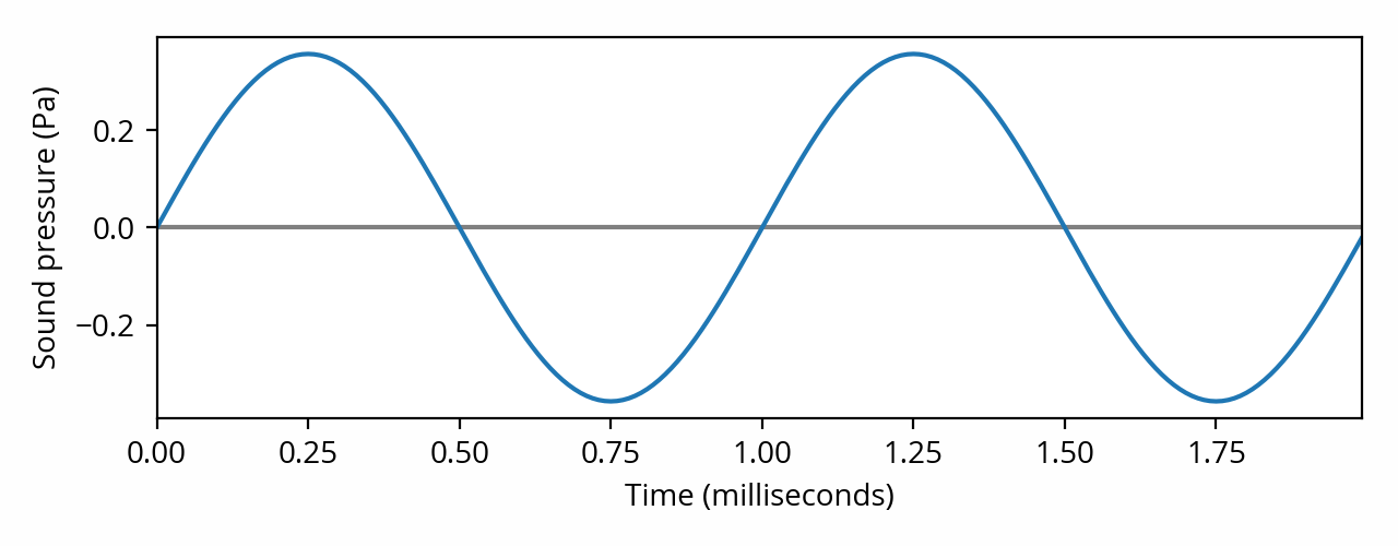
Note the change of vertical scale. We’re not dealing with voltage anymore — amplitude takes the form of sound pressure instead. Indeed, sound is a physical phenomenon in which transient changes in pressure (compression, rarefaction) produced by the vibration of a sound source propagate through the space around it. In other words, it is a longitudinal wave. Sound pressure, expressed in Pascals (Pa), quantifies the difference between normal atmospheric pressure and some local, dynamic change in pressure, at a given point in time and space. The human ear is equipped to detect these changes, which are then — finally! — perceived as sound by the human brain.
An ideal transducer will produce sound pressure proportional to the voltage applied to it, like in the above waveform. However, it is difficult to design a driver that is capable of doing that across the entire range of audible frequencies. Consequently, a number of transducer types are available, which are commonly referred to as subwoofers, woofers, midranges and tweeters.
In order to reproduce the entire range of human hearing, several of these drivers — often two or three — are assembled inside a single “box”, called the enclosure. In most designs the drivers are mounted flush with one side of the box, which is called the front baffle. An electrical circuit called a crossover splits the input signal into the frequency ranges appropriate for each driver. The resulting device is called a loudspeaker.
What I’ve described here is called a passive loudspeaker, which is the most common type in consumer “Hi-Fi” systems. Sometimes the amplifier and speaker are integrated into the same device; this is called an active or powered speaker. Examples include professional “studio monitor” speakers, which have line-level inputs. Other products, such as “Bluetooth speakers”, go one step further and throw in a DAC as well for a completely integrated solution.
Headphones are a special case and typically only have one driver per channel, which makes them simpler. Conceptually, a headphone is akin to a miniature loudspeaker. Because of their proximity to the ear, they don’t have to produce as much sound pressure; therefore they require much less power to operate (often less than 1 mW).
One notable aspect of the acoustic realm is that sound propagates in all three dimensions — the audio signal (sound pressure) is not the same at every point in space. In particular, speakers exhibit radiation patterns that vary with angle and frequency, and the sound they emit can bounce off surfaces (reflection). This in turn means that they interact with their environment (the listening room, or, in the case of headphones, the listener’s head) in ways that are complex and difficult to predict but nonetheless have an enormous impact on how the radiated sound will be perceived by a human listener. This makes choosing and configuring a speaker system quite the challenge. Hopefully, future posts on this blog will provide some pointers.